Design of the ring groove
The purpose of the ring groove is to absorb the forces transmitted from the retained machine component into the Seeger retaining system. As shown in Figure 11, the groove is preferably identified by the groove diameter d2 and, dependent on it, by the groove depth t and the groove width m.
Figure 11. Seeger ring groove
Groove diameter d2, and groove depth t
The values given in the data charts for the groove diameter d2 lead to ring fits in their grooves with a relatively large prestress. This prestress is always required when large mass forces occur in the ring plane which oppose the stress of the rings, e.g. centrifugal forces at high shaft speeds. Here, the groove depth t can be reduced in favour of an increased prestress. In designs in which such mass forces do not occur, the groove depth and thus the groove area AN and also the load bearing capacity of the groove FN can be enlarged. The limit is posed by the diameter in unstressed condition d3 i.e. for shaft rings
d2 minimo = d3 max and for bore rings d2 max = d3 min
Groove width m
The values given in the data charts are minimum values which are recommended for the usual applications of Seeger retaining systems in rectangular grooves and for unilateral force transmission. Depending on the design of the machine component pressing on the ring, the groove may be widened towards the relieving side. Wide grooves are much easier to recess than narrow ones. However, if the Seeger retaining system is to alternately transmit the forces onto the groove walls in both directions, the groove width m must largely be adapted to the ring thickness in accordance with manufacturing possibilities.
Shape of the groove
The rectangular groove is still the standard form. It can be rounded on the load side with r = 0.1 s (10% of the ring thickness s) without noticeably influencing the fit of the ring (see Figure12a).
Figure 12: groove shape
a = rectangular groove
b = slanted groove
c et d = rounded grooves
e = groove with relief groove
Figure 12b shows a groove slanted towards the relieved side. Figures 12c and 12d show grooves systematically rounded on the load side. Here, sharp-edged rings make optimum user of the groove area. Figure 12e depicts a groove with a relief groove reducing the notch effect.
Notch effect of the groove
Matching sharp-edged grooves for Seeger retaining rings leads to a notch effect. In the case of materials with a notch sensitivity corresponding to CK 45 Rm = 630 N/mm2, the following notch effect figures can be expected on a rectangular groove:
Shaft diameter:
30 mm: ß K = 2,24
80 mm: ß K = 2,60
These notch effect figures can be reduced by rounded grooves as shown in Figures 12c and 12d and by a relief groove as shown in Figure 12e.
Compensating axial play
As explained in Section 4, group 4, it is not possible using normal, flat Seeger retaining systems to assemble machine components without axial play. Attention has been drawn to elastic compensation of play with the aid of rings in group 4. Axial compensation, i.e. a springing effect of the rings, is not permissible in all designs. In this case, it would be possible to use Seeger bevelled rings which permit play-free retaining of the machine component. The use of selected thicknesses of Seeger retaining systems is possible to rigidly reduce play in steps. These mostly ground rings are available in graduations and thickness tolerances of between 0.025 mm and 0.05 mm. Support washers can also be manufactured with graduated thicknesses. Seeger-Orbis should be consulted before defining the largest and smallest thicknesses.
Positive radial retention of Seeger retaining systems
Viewed axially, the Seeger ring joint is a positive one. However, radially, the elastic ring is held in the groove only by its own tension. Positive radial retention of rings in the groove may be advantageous in the event of high axial forces and when placing high demands on safety, namely:
- The ring cannot work its way out of the groove.
- Use of deeper grooves means that there is no need for prestress and thus the groove has a greater load bearing capacity,
- circular contact is provided in the groove and
the speed dependency of the shaft rings is eliminated.
Fig. 13 Overlapping of a Seeger ring (left) and a circular wire circlip (right)
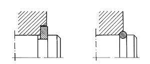
On the left, Figure 13 shows overlapping of a Seeger ring and on the right, of a circular wire ring. The latter can also be overlapped with a chamfer instead of the quarter circle-shaped recess. More or less a centrical design of the rings is a precondition for overlapping. This is ensured by all circlips, by the Seeger V rings and by the K rings. In the case of Seeger-Rings to DIN 471/472, this applies only to the versions shown on Pages 22 41, left Illustration. Overlapping of the fitted ring as shown in Figure 13 is only possible when the machine component can be pulled back before assembly and pressed on again later, a precondition which is not always fulfilled. The Seeger Handbook gives further indepth Information on design details of Seeger-Ring assemblies.


Ball bearing disc springs, Slotted and plain")