For normal Seeger ring applications, calculations are not necessary because the data chart contains all important Information.
The following calculations must be performed for special applications:
1.1 Calculation of the Seeger ring assemblies load bearing capacity
- Load bearing capacity of the groove FN
- Load bearing capacity of the Seeger ring FR
1.2 Detaching speed of Seeger rings for shafts nabl
1.3 Axial displacement of the secured machine component
1.1 THE LOAD BEARING CAPACITY OF A SEEGER RING ASSEMBLY
As regards the load bearing capacity figures given in the data charts for Seeger-Rings FN and grooves FR in each case the weaker design element is decisive with respect to the assemblies load bearing capacity. The load bearing capacity figures contain no safety factor against yield under static stresses and against fatigue fracture in the event of swelling stresses. At least a triple safety factor is provided against fracture under static stresses.
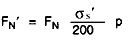
Load bearing capacity of the grove FN
Where:
σs = 200 N/mm2 (referred to grooved material)
q = 1,2 con n/t =3
S = 1
Conversion:
If the material used has a different yield Re the following applies:

If the groove depth t' or groove area AN' deviates due to a different groove diameter and/or nominal diameter d1 or due to groove edge rounding, the following applies:
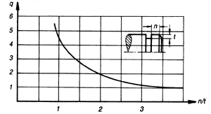
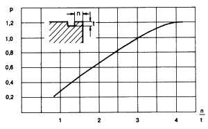
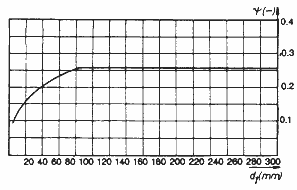
In the event of shoulder length ratios n/t <= 3, the values FN must be multiplied by the compensation factor given in the diagram in Figure 2.
Example
Sought:
load bearing capacity of the groove of Seeger ring A 20 consisting of material St 50 (σs' = 270 N/mm² shoulder length ratio n/t=2
FN(from data chart) = 5.0 kN
p (from fig.2) = 0.65
FN'=4.4 kN (no safety factor)
Load bearing capacity Fr and FRg of the Seeger ring
Two load cases are distinguished:
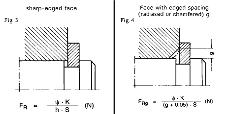
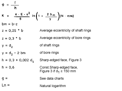
Fig.5: dished Seeger ring
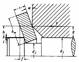
Fig. 6: Permissible dishing angle of Seeger-Rings
The values in the dats charts apply to:
Seeger-Ring material with a modulus of elasticity
E = 210 kN/mm2
FR = load bearing capacity with sharp-cornered abutment
FRg = load bearing capacity with a corner distance g
Conversion:
When using a different material for a Seeger-Ring with a different modulus of elasticity E', the following applies:
Example:
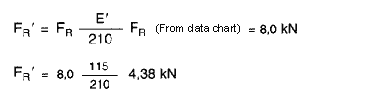
The load bearing capacity of Seeger-Ring J 22 consisting of the material bronze CuSn 8 with a modulus of elasticity E' = 115 N/mm2 and for sharp-edged abutment is to be calculated.
If the existing chamfer, rounded corner or corner distance g' deviates from the values g in the data chart, the following applies:
Important:
If, at low g' values, the value F'Rg' is greater than FR, then FR applies!
Example:
The load bearing capacity of Seeger ring A 40 is to be calculated with a chamfer on the located machine component of g' = 1.0 mm.
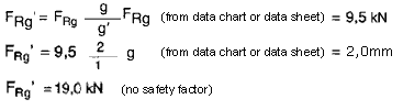
Corner distances, which reduce the ring's load bearing capacity, may also result from large-scale differences between d1 and d'1 (Figure 7)
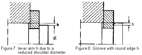
Example:
Testing the load bearing capacity of a Seeger-Ring A 40 for applications in accordance with Figure 7. The diameter reduced in comparison with d1 is aimed at facilitating ring assembly and dismantling of the machine component.
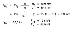
Since FRg' is greater than FR, then FR applies as the ring's maximum load bearing capacity, i.e. the corner distance resulting from d1'does not reduce the load bearing capacity.
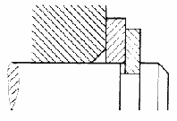
If the existing forces cannot be absorbed because of excessive lever arms g, a sharp-edge abutment must be created by inserting a Seeger support washer (Figure 9).
Fig.9: Seeger support washer between Seeger-Ring and machine component
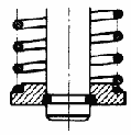
Load bearing capacity of circular wire circlips to DIN 7993:
No load bearing capacity information is given in the data charts. If overlapping rings are used (Figure 10), the load bearing capacity of the assembly depends only on the strength of the shaft and housing materials and is independent of the ring itself. When installing overlapping rings, pay attention to the radial component resulting from the axial force.
Fig.10: Overlapping circular wire circlip to DIN 7993
The groove's load bearing capacity is calculated as follows:
The safety factor S should be at least 1,25. As a rule, the smaller groove area of the shaft must be calculated for the groove area
AN = π/4(d12-d22)
1.2 DETACHING SPEED nablOF SHAFTS RING
This equation applies to the following rings:
Seeger-Rings DIN 471
Seeger circlips DIN 5417
Seeger circlips SW
For the following rings, the result must be multiplied by 0.95: Seeger-K-Rings
Seeger-V-Rings
Seeger-L-Rings
The detaching speed is the speed at which the ring opens due to the centrifugal forces acting on it and begins to separate from its fit in the groove. If cannot be expected to spring off until the speed is further increased by 50%. The values given in the data charts of all shaft rings apply to steel rings and, for bronze rings, the figures must be multiplied by 0,7.
If the speed involved is higher than the detaching speed, please consult the Seeger-Orbis technical advisory service. By overlapped assembly with the aid of a turned recessed (Figure 10), centrically restricted rings such as Seeger-K-Rings, Seeger-V-Rings and Seeger circlips can be held in the groove by a form fit and can be used at speeds above the detaching speed (see also Section "Design details").
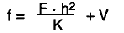
1.3 AXIAL DISPLACEMENT f
where: F = axial force
h = see below
K = see 6.1
V = 0,02 4 0,05 [mm]
The initial displacement V is 0,02 to 0,05 mm and takes smoothing of the forces pressing on each other into account.
The following applies to the lever arm:
Sharp-edged abutment:
h = 0,3 + 0,002 d1 (mm)
Abutment with corner distance:
h = 0,05 + g (mm)
Example:
Seeger-Ring AK 80
Data chart 16
Axial Force F = 12 kN
Corner distance g = 3 mm
h = 0,05 + 3 = 3,05 mm
K = 236,3 kN mm
= 12 · 3,052 / (236,3) + (0,02 / 0,05)
f = 0,49 / 0,52 mm
If it is found that the displacement is too high at a given force f, either the quadratically effective lever arm h must be reduced by design changes or the calculatory value K must be increased by using a reinforced Seeger ring.


Ball bearing disc springs, Slotted and plain")